

1. Introduction
The core component of an LED display is the light-emitting diode (LED), which, like a standard diode, has a forward conduction characteristic—meaning it has both a positive (anode) and a negative (cathode) terminal. With increasing market demands for LED displays, such as longer lifespan, consistency, and energy efficiency, the use of common cathode and common anode configurations has become widespread in various applications. To help you better understand these two technologies, this article will provide a detailed overview of their relevant knowledge.
2. Key Differences Between Common Cathode and Common Anode
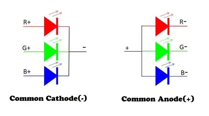
In a common cathode setup, all LED cathodes (negative terminals) share a common connection, while each anode is individually controlled by voltage. In contrast, common anode configurations connect all LED anodes (positive terminals) to a shared point, with individual cathodes managed through voltage control. Both methods are used in distinct circuit design scenarios.
Power Consumption:
In a common anode diode, the common terminal is connected to a high voltage level and remains active whenever a high voltage is required. On the other hand, in a common cathode diode, the common terminal is connected to the ground (GND), and only a specific diode needs to receive a high voltage to operate, effectively reducing power consumption. This reduction in power consumption is particularly beneficial for LEDs that are used for extended periods, as it helps to lower the screen temperature.
Circuit Complexity:
Generally, in practical engineering applications, common cathode diode circuits tend to be more complex than common anode diode circuits. The common anode configuration does not require as many high-voltage lines for driving.
3. Common Cathode
3.1 What is Common Cathode
A common cathode configuration means that the negative terminals (cathodes) of the LEDs are connected together. In a common cathode circuit, all LEDs or other current-driven components have their cathodes connected to a shared point, often referred to as “ground” (GND) or the common cathode.
3.2 Working Principle of Common Cathode
Current Flow:
In a common cathode circuit, when one or more output terminals of the control circuit supply a high voltage, the corresponding LEDs or components’ anodes are activated. At this point, current flows from the common cathode (GND) to these activated components’ anodes, causing them to light up or perform their respective functions.
Control Logic:
The control circuit regulates the state of each LED or other components (on or off, or other functional states) by changing the voltage level (high or low) at its output terminals. In a common cathode circuit, a high level typically indicates activation (lighting up or performing a function), while a low level indicates deactivation (not lighting up or not performing a function).
4. Common Anode
4.1 What is Common Anode
A common anode configuration means that the positive terminals (anodes) of the LEDs are connected together. In such a circuit, all related components (such as LEDs) have their anodes connected to a common anode point, while each component’s cathode is connected to different output terminals of the control circuit.
4.2 Working Principle of Common Anode
Current Control:
In a common anode circuit, when one or more output terminals of the control circuit supply a low voltage, a path is created between the cathode of the corresponding LED or component and the common anode, allowing current to flow from the anode to the cathode, causing the component to light up or perform its function. Conversely, if the output terminal is at a high voltage, the current cannot pass through, and the component does not light up.
Voltage Distribution:
In applications like common anode LED displays, since all LED anodes are connected together, they share the same voltage source. However, each LED’s cathode is independently controlled, allowing precise control over each LED’s brightness by adjusting the output voltage and current from the control circuit.
5. Advantages of Common Anode
5.1 High Output Current Capacity
Common anode circuit structures are relatively complex, but they have a higher output current capacity. This characteristic makes common anode circuits suitable for applications that require high power output, such as power transmission lines or high-power LED drivers.
5.2 Excellent Load Balancing
In a common anode circuit, since all components share a common anode point, the output current is more evenly distributed among the components. This load balancing capability helps reduce mismatch issues, improving the overall efficiency and stability of the circuit.
5.3 Flexibility and Scalability
Common anode circuit designs allow for flexible addition or removal of components without the need for significant adjustments to the overall circuit structure. This flexibility and scalability provide a clear advantage in complex systems and large-scale applications.
5.4 Simplified Circuit Design
In some applications, a common anode circuit can simplify the overall design of the circuit. For example, when driving LED arrays or 7-segment displays, a common anode circuit can control multiple components with fewer pins and connections, reducing design complexity and cost.
5.5 Adaptability to Various Control Strategies
Common anode circuits can accommodate various control strategies. By adjusting the output signals and timing of the control circuit, precise control of each component in the common anode circuit can be achieved to meet different application requirements.
5.6 Improved System Reliability
The design of common anode circuits emphasizes load balancing and optimized current distribution, which contributes to overall system reliability. In long-term operation and high-load conditions, common anode circuits maintain stable performance, reducing failure rates and maintenance costs.
6. Common Anode Setup Tips
Ensure that the common anode voltage is stable and sufficiently high to drive all connected components.
Design the output voltage and current range of the control circuit appropriately to avoid damaging components or degrading performance.
Take into account the forward voltage drop characteristics of LEDs and ensure enough voltage margin in the design.
7. Advantages of Common Cathode
7.1 High Power Capability
Common cathode circuits can combine the output signals of multiple electronic devices, resulting in higher output power. This makes common cathode circuits particularly advantageous in high-power output scenarios.
7.2 Versatility
The input and output terminals of a common cathode circuit can be freely connected, allowing it to be applied flexibly to various electronic devices. This versatility provides common cathode circuits with wide-ranging applications in the field of electronic engineering.
7.3 Ease of Adjustment
By adjusting components such as resistors or transformers in the circuit, the operating state and output signal strength of a common cathode circuit can be easily modified. This ease of adjustment makes common cathode circuits popular in applications requiring precise control of output signals.
7.4 Power Consumption Control
In LED display applications, common cathode circuits can precisely distribute voltage, effectively reducing power consumption. This is achieved because common cathode circuits allow direct voltage supply according to each LED’s specific requirements, eliminating the need for voltage-dividing resistors and reducing unnecessary power loss and heat generation. For example, common cathode technology can reduce the operating voltage of LED chips from 4.2-5V to 2.8-3.3V without affecting brightness or display performance, which directly reduces the power consumption of fine-pitch LED displays by more than 25%.
7.5 Enhanced Display Performance and Stability
Due to the reduced power consumption, common cathode circuits lower the overall screen temperature. The stability and lifespan of LEDs are inversely proportional to temperature; therefore, lower screen temperatures lead to higher reliability and longer lifespan for LED displays. Additionally, common cathode technology reduces the number of PCB components, further enhancing system integration and stability.
7.6 Precise Control
In applications requiring precise control of multiple LEDs or other components, such as LED displays and 7-segment displays, common cathode circuits enable independent control of each component. This precision control capability makes common cathode circuits excel in both display performance and functionality.
8. Common Cathode Setup Tips
When using common cathode 7-segment displays, avoid direct contact with the surface and handle the pins carefully. Pay attention to soldering temperature and time to ensure soldering quality. Also, ensure that the operating voltage and current are matched, ground the common cathode properly, and consider the microcontroller’s driving capability and delay control. Additionally, pay attention to the protective film, compatibility with the application scenario, and the stability of system integration to ensure the normal operation and extended lifespan of the common cathode 7-segment display.
9. How to Identify Common Cathode vs. Common Anode
9.1 Observe the LED Pins:
Generally, the shorter pin of an LED is the cathode, and the longer pin is the anode. If the microcontroller connects the longer pins together, it is using a common anode configuration; if the longer pins are connected to the microcontroller’s IO ports, it is using a common cathode configuration.
9.2 Voltage and LED Status
For the same LED, with the same port output voltage, if “1″ lights up the LED and “0″ turns it off, it indicates a common cathode configuration. Otherwise, it is a common anode configuration.
In summary, determining whether a microcontroller uses a common cathode or common anode configuration involves examining the LED connection method, the LED’s on/off state, and the port output voltage. Identifying the correct configuration is essential for proper control of LEDs or other display components.
If you want to know more about LED displays, contact us now. RTLED will answer your questions.
Post time: Aug-24-2024